Saturday, October 18, 2014

10/16/2014 Collisions In Two Dimensions

Purpose:

The purpose of this lab is look at a two dimensional collision and determine if the momentum and energy are conserved with a marble on marble and a steel ball with marble.

Experiment:
The first experiment we did was a collision with a steel ball and a marble. We get the data we needed by filming the collision of  the balls on a smooth level surface. We gently sent one ball colliding with a stationary ball create an angle of separation after the balls collision. Here is a picture of the stet up described.


Here is the first video of the collision of the marble hitting the steel ball at rest and the second video of the marble hitting the marble at rest.


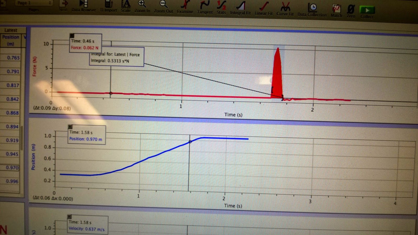
We then used a feature in Logger Pro to plot points of objects during time intervals. So we plotted points on the video for the position of each ball for each period of a second. We also set a known length in the video to a measurement and change the x axis of the video to be align with the positive direction with the first ball moving. Then with this data we can let Logger Pro calculate position vs time by measured distance we set on the video.

Here is the data for the first collision with the marble hitting the steel ball. The data is as follows

First ball (marble) velocity (m/s)
Yo = 0;
Xo = 0.5128 m/s

Yf = 0.06326 m/s
Xf = -0.08789 m/s

Second ball (steel) velocity (m/s)
Yo = 0
Xo = 0

Yf = -0.03030 m/s
Xf = 0.1353 m/s

Here is the data for the second collision with the marble hitting the marble. The data is as follows

First ball (marble) velocity (m/s)
Yo = 0;
Xo = 0.0.4847 m/s

Yf = -0.1578 m/s
Xf =  0.2849 m/s

Second ball (steel) velocity (m/s)
Yo = 0
Xo = 0

Yf = 0.1337 m/s
Xf = 0.1496 m/s


Now to check if the energy was conserved we plotted a graph with calculated values for Momentum on X-axis, Momentum on Y-axis, and Kinetic Energy.


Marble hitting steel ball:
The orange dotted line on top is Momentum X vs time.
The purple dotted line on the bottom is Momentum Y vs time.
The blue dotted line in the middle is kinetic energy vs time.

The kinetic energy line should be straight to show energy is conserved which isn't bad as shown below.

Marble hitting marble:
The black dotted line on the top is Momentum X vs time.
The light blue dotted line on bottom is Momentum Y vs time.
The green dotted line in the middle is kinetic energy vs time.

The kinetic energy line should be straight to show energy is conserved which isn't bad as shown below.

Results:
Overall I think the experiment was a success and our lines are not perfectly straight to show energy was conserved because of the clicking on each location of the ball is not exact and was very tedious to do. If we had bigger intervals maybe the line would be straighter or if the computer could just locate the location for us it would work better. Either way I think our results show energy is conserved.

10/9/2014 Impulse Momentum Activity

Purpose:
This lab purpose is to find the objects impulse which is applied to an objects that equals the change in momentum of that object. To do this we will use two carts to measure the force impact and the velocity of the cart.

Experiment:
In this lab we set up a cart attached to a pole so we could use the spring it has inside the cart to measure impact with another cart which has a force sensor. So the moving cart will collide into the station cart with the spring and allows the initial cart to be pushed back after the collision. During the collision we measure the non constant force and the carts non constant velocity before during and after the impact. Here is a picture of the experiment.


Here is the data of the force, position, and velocity of the moving cart which is the blue cart in the picture being pushed and bouncing back. Are force sensor is reading a negative force in this picture, but we reverse the sensor and repeated the experiment. As you can see the collision is less than 1/5th of a second.

Now that we have the data collected we can calculate the impulse of the carts collision by taking the integral of the change in Force respect to time from begging of collision to the end(momentum). We repeated the experiment against with the force being positive then increased the mass of the car and did the experiment again. The integral of the momentum is simply the area under the graph as shown below.

M = 403 grams

With our own calculations we have:
m = 403 g
Vo = 0.48 m/s
Vf = -0.38

m(Vf - Vo) = Impulse
0.403(-0.38 - 0.48) =  -0.346

M = 803 grams


With our own calculations we have:
m = 803 g
Vo = 0.633 m/s
Vf = -0.5

m(Vf - Vo) = Impulse
0.803(-0.5 - 0.633) =  -0.907

Both experiments our signs where wrong but this is because we flipped the force sensor sign and not the position sign.

The next part of the impulse lab we used a clay block instead of a cart with a spring for the impact object. So now when the cart collide it will stick into the clay and not bounce back. Here our the graphs. You can see in the data collection the position does not change back and the velocity stops suddenly so the energy is not conserved. The integral Force respect of time to find the impulse of the impacts.

Mass 403 grams


Mass 803 grams

Wednesday, October 15, 2014

10/9/2014 Unknown magnet energy.

Purpose:
The purpose of this lab is to find some kind of energy relation from a magnet which does not fit hooks law for potential and kinetic energy. To do this we will have to measure the force vs distance to find the work and then get an equation to test if energy is conserved.

Experiment:
The experiment was setup with a slider which is on an air table to create a frictionless surface for it to move on. One of the problems was making sure the table was level enough so the slider wouldn't stop because of the slope of the table. After we had the table at a reasonable level we tested the slider by pushing it into the side of the table with the magnet which would repel the magnet on the glider back to its original starting point. Here is a picture of the setup:


Next we put the air table on a slope so the glider would slide into the magnet and we calculated the angle of the slope. Then we would measure the separation distance from the magnet. Now with the weight of the glider  and the angle we could find the force with equation:

mgh * cos(x)   =  ma = Force   *x is the angle

Here is the table at the angle:


We did this five more times increasing the angle and measure the angle and distance so would could graph the force vs the distance. With this graph we put a non linear fit for the computer to find the values of A and B so we could create an equation for the relationship of the magnets energy.


Now we took the information from the force vs distance graph and derived out formula which we will use to calculate the energy of the magnet. 

Next we leveled our table and pushed the glider into the magnet again but this time measure with our motion sensor so we can measure velocity, position, and time.

We setup up another graph to graph potential energy, kinetic energy and total energy. Where potential energy is from the magnet.

Here is our final graph:

The final graph show the kinetic energy in purple is conserved with the potential energy of the magnet.


Sunday, October 12, 2014

10/7/2014 Conservation of Energy

Purpose:

The purpose of this lab is show the the conservation of energy. To do this we will need to measure the kinetic energy of the mass, kinetic energy of the spring, potential energy of the mass, potential energy of the spring, the elastic energy of in the spring, gravitational potential energy of the spring, and finally the total of all the energy.

Experiment:

To show the conservation of energy we will be using a mass attached to a spring. We will measure the springs natural length and the then measure the springs stretch to find the springs constant coefficient by using the formula mg = kx.

Now we use our motion sensor which is position on the floor to measure the distance the mass will oscillate up and down on the spring. We bring the mass to the springs natural length and let logger pro measure our time and distance which gives us velocity.

Here is a picture of the experiment setup:


Now that we have all our data collected from our motion sensor we had to calculate the six forms of energy we need to get the total energy on the system.

Here are the formulas we used to created calculated tables for each type of energy.

KE of mass : 1/2mv^2
PE of mass:   mg * y
Elastic PE in spring: 1/2 K (stretch)^2
PE of spring: m(spring) / 2 * g * y + mgh/2  *h  = height of top of spring and y = bottom of spring
KE of spring 1/2 m(spring)/3 * V^2(mass)
GPE: 1/2 m(spring) * g * y (y = bottom of mass height)

Then we where able to calculate the total energy in the system and graphed all this data on logger pro vs time.


At this point we realized the way we collected the data was wrong because we zero our motion sensors at the position of reset and reversed the position sensor so our distance would be positive going down. So we had to ask the professor for help to change our distance readings and we where  calculate our data properly as shown in the graph below the top line is the conservation of of potential and kinetic energy in the system which creates an almost straight line.


Saturday, October 4, 2014

10/2/2014 Work-Energy Theorem

Purpose:
Today we looked at the Work-Energy Theorem which is the work is equal to the total kinetic energy.

Experiment:
We are going to attempt to show this relationship in our lab by taking a spring attached to a rolling cart  and attached to force sensor on the other side of the spring and start the car at rest to zero the distance of our motion detector. We also had to make sure our force sensor was zeroed and was measuring close to a known mass. So now we have a cart attached to a spring at rest pointing to location zero. We then stretch the spring out and hold the cart in position and tell our motion sensor that towards the resting position which is zero is our positive axis. So the cart is pulled away from the resting position show an increase of distance not a negative distance. We pull the cart back again turn on the sensor to collect data and let the cart go.

Here is a picture of our setup.


Calculations:
 Now we have all the data collected into our logger pro program from our motion sensor and force sensor we have force, time, position, and velocity, so all we need now is the Kinetic Energy which we add a calculated variable into logger pro using the formula KE = (mv^2)/2. Which our kinetic energy now calculated we plot a graph with kinetic force vs position and also plot a separate graph on the same graph for kinetic energy. We then select a portion of our graph for force vs position to get the area by using the integral of the selected portion of our graph which should give us the the same kinetic energy for the same time. It is no perfect but we feel our data is has a reasonable error.

Results:
Here is our graph red is force vs position and purple is kinetic energy. You can also see our integral compared to the kinetic energy for that time.