Friday, December 5, 2014

12/2/2014 SHM

Purpose:

The purpose of this experiment is to calculate the period of half circle piece of cardboard.

Experiment:

The first part of our experiment is cut out a half circle from cardboard to use for our simple harmonic motion.

Once we cut out the half circle we had to calculate the inertia from the the top and bottom of the half circle.

We used to calculus to solve inertia from the center of mass and then made the proper shifts to find the inertia from pivot of top and bottom.

Here is our calculation for inertia from center of mass.


We then created a formula to calculate the period of the using SHM.

The mas of our half circle is 0.0058kg with a radius of 0.1075.

Once we had both formulas we then predicted the period of SHM from the top as 0.714 seconds and from the bottom as of 0.613 seconds.

Here is a picture of our calculation.


 Here is a picture of are system we used a motion sensor to measure the periods which we found for the bottom 0.764s and from the top 0.694s


For the period from the pivot on the bottom we where off by 6% and for the period with the pivot on the top we where off by 11%.


11/25/2014 Mas Spring Oscillations Lab

Purpose:

For this lab we are going to test how the period of a spring with hanging mass is affected by the spring constant and or the hanging mass.

Experiment:

In this lab the class separated into eight groups where four groups would share there measured information with in the four groups.

Each group of the four had unique spring with separate spring constant values. To make sure we all usable reading we had to make sure all our spring weight was the same so every one had to add weight to our system to make sure the values where good. We did this by taking the heaviest spring and taking a third of the mass  so all one third of the spring mass was equal.

Our group had to add 5g to our system to make up for the heavier spring.

First part we had to measure the spring constant which we did by attaching a hanging mass to our spring and measure the acceleration due to gravity and spring constant. We used a motion sensor below the mass to measure its acceleration.

The formula we used was

mg - kx = ma

Our K value was 5.0405

Our mas of our spring is 11g

Here is a picture of our system to measure the spring constant.

Now we used our motion sensor to measure the period of the mass and spring on our system with logger pro. We did this by measure the distance it would travel and the time it would take to go and down.

We repeated this experiment four time increasing the mass. Mass is the mass we had to add to a 100g hanging mass. Period is in seconds

Mass     Period
05g        0.95 s
55g        1.1   s
105g      1.3   s
155g      1.4   s


Next we got the information from the other groups to graph the change of period due to mass and spring constants.

Here is our graph period vs mass which shows as the mass increases the period also increases.
This graph is of only our spring system.


Next is period vs spring constant of the hanging mass 100g and the added mass to make the system equal for all springs. With higher spring constants the smaller the period of the system be.


11/20/2014 Conservation of Linear and Angular Momentum

Purpose:

The purpose of this experiment is to show how linear and angular momentum can be transfered to solve equation involving colosions which produce angular motions.

Experiment:

For this experiement we are going to have a metal ball slide down a ramp and collide into our rotating disk aperateus. We first had to measure the value of inertia for our aperateus which will have the ball colide into to create an angular motion. To do this we took a known mass attached to a string which we then wrapped around our aperateus. Then we used a motion sensosr to find the angular acceleration of the system. We then used the angular acceleration, known hanging mass, known aperateus mass, and the radius where the string wraped around to find the inertia of the aperateus.

Here is the aperateus with the hnaging mass.

Here is our measured angular acceleration:

With our known mass and the average angular acceleration we solved the inertia value of the aperatus shown below.


Know we took the ramp which the ball will roll down on and took measurements of the device so we can determine the height the ball will travel down and then we had to calculate the velocity at which the ball left the ramp.

To calculate the height we just measured the ramp with a meter stick.

To measure the velocity we measured the height of the bottom of the ramp to the floor with a meter stick and took a sheet of carbon paper to mark the landing distance away from the table of the ball.

With that all set up we let the ball roll down the ramp to hit the sheet of carbon paper a couple of times to get the average distance from the end of the ramp to the landing distance on the floor.

With this data we used conservation of energy to calculate the velocity of the ball leaving the ramp.


Here our some measured data we where given for the ball and hanging mass. Also some ramp height measurements are shown.


To the floor from the bottom of the ramp is 95.5cm and the ball landed a length of 52.2 cm from the end of the ramp to the distance parallel to the table top on to the floor.

Here is our energy calculation to find the velocity the ball left the ramp assuming the ball did not slip at all.

Now we had enough information to predict the final angular velocity of the apparatus after collision of the rolling ball down the ramp. Here is our prediction of all the gathered data using conservation of angular momentum.


Finally we performed the experiment measuring the angular velocity of the apparatus after collision.

Here is the apparatus  for collision and our ramp.


Here is our actual values from the experiment which are very close to our prediction.

Actual : 1.775 rad/s
Prediction: 1.95 rad/s


Sunday, November 30, 2014

11/18/2014 Angular Momentum

Purpose:

The purpose of this lab was to learn angular momentum with an our expierment by first breaking our problem down to three steps and predicting the final height of our experiement.

Experiment:

The first part of experiment was setting up the equipment which included a meter stick, a clay ball, a stand to hold the meter stick which is spun on, and another stand to hold the clay ball.

The purpose of the device is raid the meter stick to a 90 degree angle and let the meter strick rotate at the other end of the stick which would allow the bottom end to collide with the clay ball.

L = 1m
clay = 37g
stick = 136 g

The first part of the experiment is conservation of angular energy.

Here is the formula for part 1:
mgh/2 = 1/2 I w^2

mgL/2 = 1/2(1/3ML^2)w^2

w = 5.422 rad/s

Once the meter stick collides with the clay ball energy is not coserved so we must use angular momentum which is conserved to figure out how fast the meter stick and the clay ball will be travling in an angular motion.

Here is the formula for part 2:
Iw = Iw
1/3(ML^2)w = (1/3ML^2 + mL^2)wf

wf = 2.9854 rad/s

After the colision we can once again use conservation of angular energy to predict how high the stick and clay ball will travel back up.

Here is the formula for part 2:
1/2(Iw^2) = Mgh/2 + mgh

1/2(1/3ML^2 + mL^2) w^2 = MgL/2 + mgh

h = 0.35527 m


Are actual height is very close to our calculated height. We had no sensors to measure the actual height, so we had to visually measure where the clay stopped.

Here is a picture of the setup described.


Saturday, November 29, 2014

11/06/2014 Moment Of Inertia

Purpose:

The purpose of this lab is to find a spinning disk moment of inertia and measure the deceleration of the disk due to friction to predict the time for a cart attached to the disk with a wire to travel down a slope of some angle.

Experiment:

Part 1:

The first objective of the lab is to come up with a formula for the the angular acceleration of the spinning disk with friction which is as follows:

Tr - Tfriction = Ia

(Torque with respect to radius - torque of friction = inertia * angular acceleration)

We than measured the diameter of the outer and inner part of our disk.

We have the mass of the device which is labeled on the disk.

Next we calculated the inertia of the disk by adding the two types of cylinder which make up the disk we are using.

Here is the calculation from part 1:


Part 2:

Then we created the predicted formula for the acceleration of the cart which will travel down the slope.

Now we used logger pro and a camera to record the declaration of the spinning disk by it self by attaching a peace of tape on the edge of the disk and measure the time for the first revolution compared to the fourth revolution to determine the declaration due to friction.

Here is the camera we used to measure the rotations with logger pro:


Then with all the information gather we where able to predict the time it would take for the cart of 500g attached to the spinning disk to travel down the known distance which we measured with a known angle which we measured.

Here is our calculation from part 2:


Here is our experiment setup of the cart attached to the disk with the ramp:

Our predicted time was 9.2 second and our actual time measured with a stop watch was 9.73 seconds.

9/30/2014 Angular Acceleration: Part 1

Purpose:

The purpose of this lab was to measure and collect data for angular acceleration  to later find the moment of inertia, but we only seeing what factors affect the angular acceleration.

Experiment:

The experiment we used an apparatus which has two rotating disks which have a number of ticks along the side which can be used to measure the angular velocity of the disks. This apparatus also has a air hose which force air in between the two disks to create an almost frictionless surface. We used another smaller attachment on top of the disk to attack a wire which will wrap the wire will wrap around and which leads over a pulley off the table attached to a hanging mass as shown in the picture below.


We measure the diameter and mass of the top steel disk, the diameter and mass of the bottom steel disk, the diameter and mass of the top aluminum disk, the diameter and mass of the smaller torque pulley, the diameter and mass of the larger torque pulley, and the mass of the hanging mass supplied the the apparatus.

Bottom Steel:
mass = 1348 g
diameter = ?

Top Steel:
mass = 1358 g
diameter = ?

Aluminum:
mass = 465 g
diameter = ?

With our now measure values we rand six experiments to find separate angular acceleration. We used the marks of the disk which was 200 for one revolution and Logger Pro with a sensor to measure the up and down acceleration and find an average acceleration.  Experiments 1,2 and 3 are of changing the hanging mass, experiments 1 and 4 show the effect of changing radius, and experiments 4,5 and 6 show the effect of the changing the rotating mass.

Here is one example of the data we collected showing the downward and upward angular acceleration:


Here is all the data we collected:

Saturday, October 18, 2014

10/16/2014 Collisions In Two Dimensions

Purpose:

The purpose of this lab is look at a two dimensional collision and determine if the momentum and energy are conserved with a marble on marble and a steel ball with marble.

Experiment:
The first experiment we did was a collision with a steel ball and a marble. We get the data we needed by filming the collision of  the balls on a smooth level surface. We gently sent one ball colliding with a stationary ball create an angle of separation after the balls collision. Here is a picture of the stet up described.


Here is the first video of the collision of the marble hitting the steel ball at rest and the second video of the marble hitting the marble at rest.


We then used a feature in Logger Pro to plot points of objects during time intervals. So we plotted points on the video for the position of each ball for each period of a second. We also set a known length in the video to a measurement and change the x axis of the video to be align with the positive direction with the first ball moving. Then with this data we can let Logger Pro calculate position vs time by measured distance we set on the video.

Here is the data for the first collision with the marble hitting the steel ball. The data is as follows

First ball (marble) velocity (m/s)
Yo = 0;
Xo = 0.5128 m/s

Yf = 0.06326 m/s
Xf = -0.08789 m/s

Second ball (steel) velocity (m/s)
Yo = 0
Xo = 0

Yf = -0.03030 m/s
Xf = 0.1353 m/s

Here is the data for the second collision with the marble hitting the marble. The data is as follows

First ball (marble) velocity (m/s)
Yo = 0;
Xo = 0.0.4847 m/s

Yf = -0.1578 m/s
Xf =  0.2849 m/s

Second ball (steel) velocity (m/s)
Yo = 0
Xo = 0

Yf = 0.1337 m/s
Xf = 0.1496 m/s


Now to check if the energy was conserved we plotted a graph with calculated values for Momentum on X-axis, Momentum on Y-axis, and Kinetic Energy.


Marble hitting steel ball:
The orange dotted line on top is Momentum X vs time.
The purple dotted line on the bottom is Momentum Y vs time.
The blue dotted line in the middle is kinetic energy vs time.

The kinetic energy line should be straight to show energy is conserved which isn't bad as shown below.

Marble hitting marble:
The black dotted line on the top is Momentum X vs time.
The light blue dotted line on bottom is Momentum Y vs time.
The green dotted line in the middle is kinetic energy vs time.

The kinetic energy line should be straight to show energy is conserved which isn't bad as shown below.

Results:
Overall I think the experiment was a success and our lines are not perfectly straight to show energy was conserved because of the clicking on each location of the ball is not exact and was very tedious to do. If we had bigger intervals maybe the line would be straighter or if the computer could just locate the location for us it would work better. Either way I think our results show energy is conserved.

10/9/2014 Impulse Momentum Activity

Purpose:
This lab purpose is to find the objects impulse which is applied to an objects that equals the change in momentum of that object. To do this we will use two carts to measure the force impact and the velocity of the cart.

Experiment:
In this lab we set up a cart attached to a pole so we could use the spring it has inside the cart to measure impact with another cart which has a force sensor. So the moving cart will collide into the station cart with the spring and allows the initial cart to be pushed back after the collision. During the collision we measure the non constant force and the carts non constant velocity before during and after the impact. Here is a picture of the experiment.


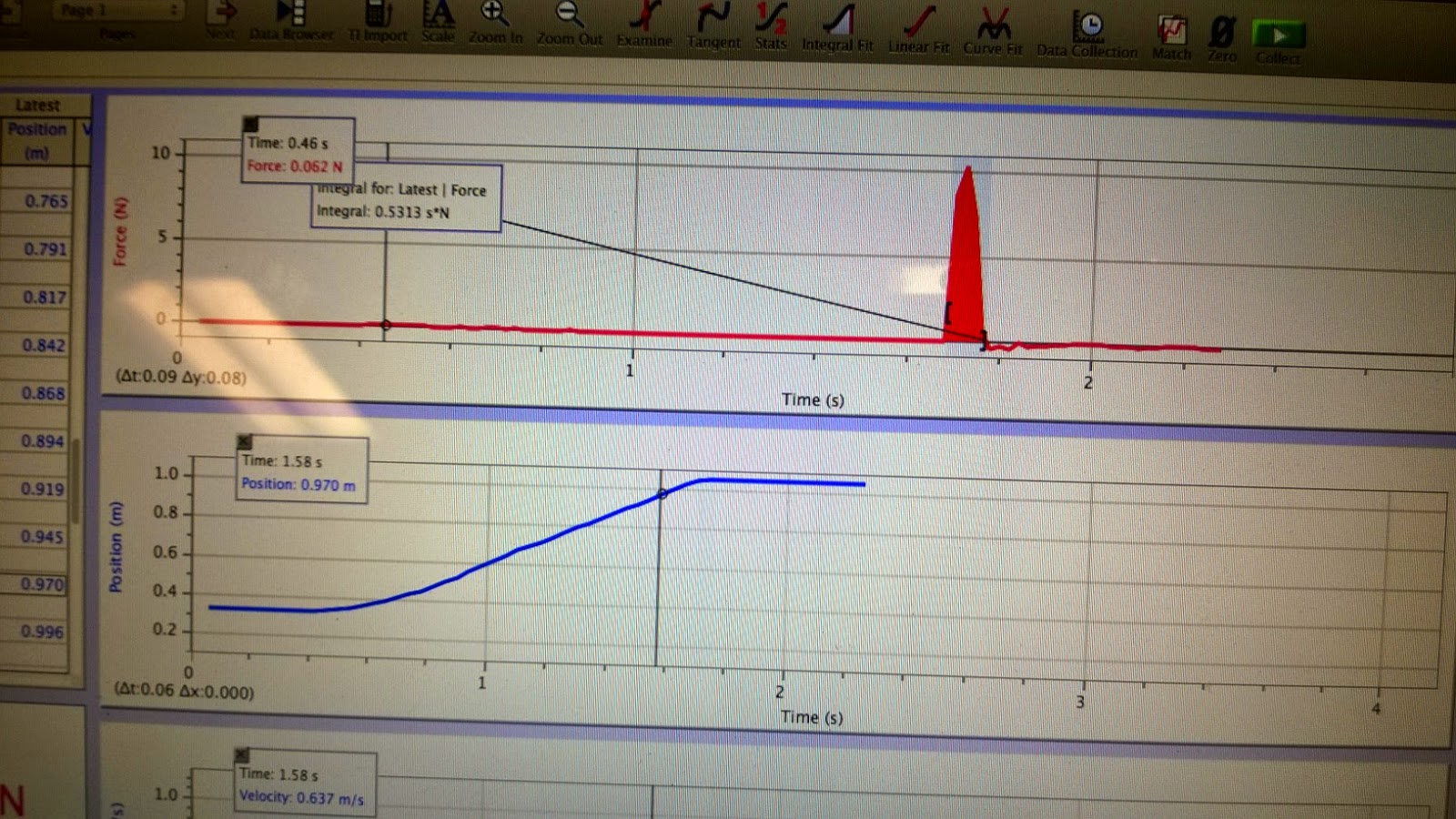
Here is the data of the force, position, and velocity of the moving cart which is the blue cart in the picture being pushed and bouncing back. Are force sensor is reading a negative force in this picture, but we reverse the sensor and repeated the experiment. As you can see the collision is less than 1/5th of a second.

Now that we have the data collected we can calculate the impulse of the carts collision by taking the integral of the change in Force respect to time from begging of collision to the end(momentum). We repeated the experiment against with the force being positive then increased the mass of the car and did the experiment again. The integral of the momentum is simply the area under the graph as shown below.

M = 403 grams

With our own calculations we have:
m = 403 g
Vo = 0.48 m/s
Vf = -0.38

m(Vf - Vo) = Impulse
0.403(-0.38 - 0.48) =  -0.346

M = 803 grams


With our own calculations we have:
m = 803 g
Vo = 0.633 m/s
Vf = -0.5

m(Vf - Vo) = Impulse
0.803(-0.5 - 0.633) =  -0.907

Both experiments our signs where wrong but this is because we flipped the force sensor sign and not the position sign.

The next part of the impulse lab we used a clay block instead of a cart with a spring for the impact object. So now when the cart collide it will stick into the clay and not bounce back. Here our the graphs. You can see in the data collection the position does not change back and the velocity stops suddenly so the energy is not conserved. The integral Force respect of time to find the impulse of the impacts.

Mass 403 grams


Mass 803 grams

Wednesday, October 15, 2014

10/9/2014 Unknown magnet energy.

Purpose:
The purpose of this lab is to find some kind of energy relation from a magnet which does not fit hooks law for potential and kinetic energy. To do this we will have to measure the force vs distance to find the work and then get an equation to test if energy is conserved.

Experiment:
The experiment was setup with a slider which is on an air table to create a frictionless surface for it to move on. One of the problems was making sure the table was level enough so the slider wouldn't stop because of the slope of the table. After we had the table at a reasonable level we tested the slider by pushing it into the side of the table with the magnet which would repel the magnet on the glider back to its original starting point. Here is a picture of the setup:

Next we put the air table on a slope so the glider would slide into the magnet and we calculated the angle of the slope. Then we would measure the separation distance from the magnet. Now with the weight of the glider  and the angle we could find the force with equation:

mgh * cos(x)   =  ma = Force   *x is the angle

Here is the table at the angle:


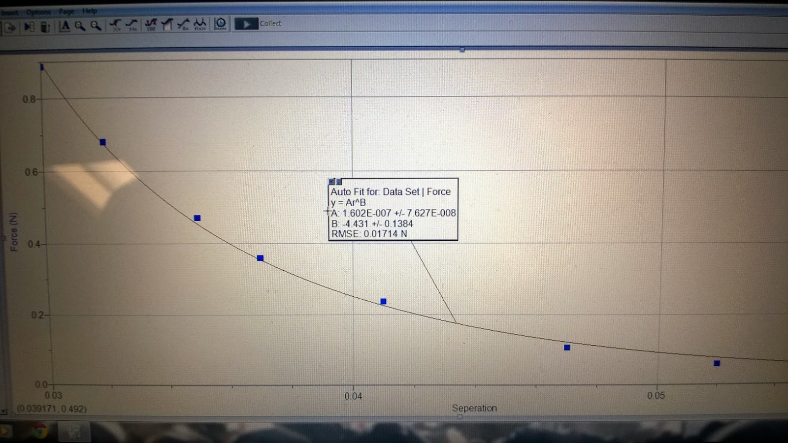
We did this five more times increasing the angle and measure the angle and distance so would could graph the force vs the distance. With this graph we put a non linear fit for the computer to find the values of A and B so we could create an equation for the relationship of the magnets energy.


Now we took the information from the force vs distance graph and derived out formula which we will use to calculate the energy of the magnet. 

Next we leveled our table and pushed the glider into the magnet again but this time measure with our motion sensor so we can measure velocity, position, and time.

We setup up another graph to graph potential energy, kinetic energy and total energy. Where potential energy is from the magnet.

Here is our final graph:

The final graph show the kinetic energy in purple is conserved with the potential energy of the magnet.


Sunday, October 12, 2014

10/7/2014 Conservation of Energy

Purpose:

The purpose of this lab is show the the conservation of energy. To do this we will need to measure the kinetic energy of the mass, kinetic energy of the spring, potential energy of the mass, potential energy of the spring, the elastic energy of in the spring, gravitational potential energy of the spring, and finally the total of all the energy.

Experiment:

To show the conservation of energy we will be using a mass attached to a spring. We will measure the springs natural length and the then measure the springs stretch to find the springs constant coefficient by using the formula mg = kx.

Now we use our motion sensor which is position on the floor to measure the distance the mass will oscillate up and down on the spring. We bring the mass to the springs natural length and let logger pro measure our time and distance which gives us velocity.

Here is a picture of the experiment setup:


Now that we have all our data collected from our motion sensor we had to calculate the six forms of energy we need to get the total energy on the system.

Here are the formulas we used to created calculated tables for each type of energy.

KE of mass : 1/2mv^2
PE of mass:   mg * y
Elastic PE in spring: 1/2 K (stretch)^2
PE of spring: m(spring) / 2 * g * y + mgh/2  *h  = height of top of spring and y = bottom of spring
KE of spring 1/2 m(spring)/3 * V^2(mass)
GPE: 1/2 m(spring) * g * y (y = bottom of mass height)

Then we where able to calculate the total energy in the system and graphed all this data on logger pro vs time.


At this point we realized the way we collected the data was wrong because we zero our motion sensors at the position of reset and reversed the position sensor so our distance would be positive going down. So we had to ask the professor for help to change our distance readings and we where  calculate our data properly as shown in the graph below the top line is the conservation of of potential and kinetic energy in the system which creates an almost straight line.


Saturday, October 4, 2014

10/2/2014 Work-Energy Theorem

Purpose:
Today we looked at the Work-Energy Theorem which is the work is equal to the total kinetic energy.

Experiment:
We are going to attempt to show this relationship in our lab by taking a spring attached to a rolling cart  and attached to force sensor on the other side of the spring and start the car at rest to zero the distance of our motion detector. We also had to make sure our force sensor was zeroed and was measuring close to a known mass. So now we have a cart attached to a spring at rest pointing to location zero. We then stretch the spring out and hold the cart in position and tell our motion sensor that towards the resting position which is zero is our positive axis. So the cart is pulled away from the resting position show an increase of distance not a negative distance. We pull the cart back again turn on the sensor to collect data and let the cart go.

Here is a picture of our setup.


Calculations:
 Now we have all the data collected into our logger pro program from our motion sensor and force sensor we have force, time, position, and velocity, so all we need now is the Kinetic Energy which we add a calculated variable into logger pro using the formula KE = (mv^2)/2. Which our kinetic energy now calculated we plot a graph with kinetic force vs position and also plot a separate graph on the same graph for kinetic energy. We then select a portion of our graph for force vs position to get the area by using the integral of the selected portion of our graph which should give us the the same kinetic energy for the same time. It is no perfect but we feel our data is has a reasonable error.

Results:
Here is our graph red is force vs position and purple is kinetic energy. You can also see our integral compared to the kinetic energy for that time.

Friday, September 26, 2014

9/25/2014 Work and Energy

Purpose:
The purpose of this lab was to get physic students some needed sunshine. So we went out side to calculate the amount of work we use to walk up a flight of stairs and how much work we use to pull an object up the same distance. We will also calculate the power as well.

Experiment:
First thing we did in this lab is measure the height of one step. Then we counted the number of steps total. With the height of the steps and the number of steps we could calculate the height we would travel up the stairs.Then we had to walk up the stairs and time how long it took us to reach the top of the stairs. That was the first part of our experiment for data for work it will take to climb the stairs. Then the next part of the lab we bags with weights in them which we would hang on a pulley over a railing. One of our team members would time the other while they pull the bag up the same height as the stairs.

Here is a picture of the class out side performing collecting data for our experiments.


After all the data was collected when went back inside to calculate our results. First thing we did was take our known weight and convert it into kg. My weight converted into kg was 95kg. Then with this I plugged in the data to the formula for work which is work = force * distance. This formula will give the results for the bad and walking up the stairs.

4.29 m is the distance to the top of the balcony floor in the picture.

Stairs:
Work:
(95kg) (9,8m/s^2)(4.29m) = 3993.99 joules
Power:
work / 8.48 second = 251.19 watts

Bag on pulley:
(5kg)(9,8m/s^2)(4.29m) =  210.21 joules
Power:
work / 8.48 seconds = 24.78 watts

The amount of work or power to bring a bag up the stairs would be much easier using the pulley system, To burn calories the stairs is a better choice.